|
 Different
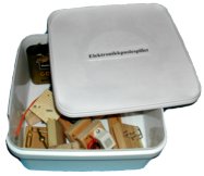
Electronic Puzzle sets have been developed during a periode of some years. It started with
different components in an ice box (2 litre) as shown to the right. The
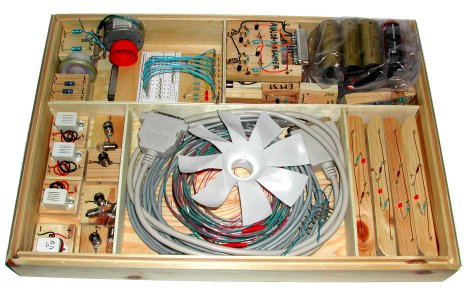
box below is the last version so long which contains four sets of the basic components
in addition to different equipments for connection to a computer and sensors
for measuring temperature and light. The box is home-made based on plywood (kryssfiner)
and wainscot (panel) and it should be easy to make such boxes in a woodwork
class in the school.
Different
Electronic Puzzle sets have been developed during a periode of some years. It started with
different components in an ice box (2 litre) as shown to the right. The
box below is the last version so long which contains four sets of the basic components
in addition to different equipments for connection to a computer and sensors
for measuring temperature and light. The box is home-made based on plywood (kryssfiner)
and wainscot (panel) and it should be easy to make such boxes in a woodwork
class in the school.
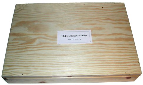
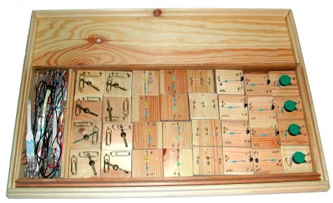
Box lid with an upper store from the main box:
The main box:
|
|
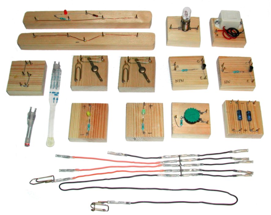
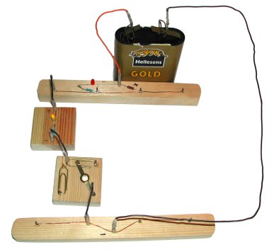
Above are the basic components in
the Electronic Puzzle,
|
1a,
1b: Current dividers (Strřmdelere)
If these are connected to the
batteri poles and the other components are connected between these, the red LED will light
up and warn if there is a short circuit or overload which may damage the battery
or other components.
2 Light Emitting Diode/LED (Lysdiode)
Note that a resistance protects
the diodes so that connecting them wrong won't damage them.
3 Light bulb (lyspćre)
The bulb should be 6V, 50mA which
means that the transistors won't overload if they supply current to the bulb.
4 Buzzer (summer)
Makes a sound.
5 Switch (bryter)
This simple homemade switch may function as a mono-stable and
bi-stable switch which can changes between two circuits, and it can therefore
represent different types of switches.
6 Variable resistor (variabel motstand)
Note that an extra resistor
protects the potensiometer. The resistance in the variable resistor then
gets a lower limit of 100Ω, but it is no problem
in ordinary circuits.
7 Contact (kontakt)
For connecting variable resistors or cables
from distance or local courses.
7a Light Dependent Resistor /LDR (lysfřlsom
motstand)
7b Temperatur Dependent Resistor / NTC (temperaturfřlsom
motstand)
Note that the spacing between the two contacts in the middle is
a standard which also is used for the shielded cables and therefore the sensors
may be placed in a distance from the main circuit.
8 Transistor (transistor)
The transistors is protected with a resistor
connected to the B-pin, and as long as the user don't let the red LED on the
current divider keep shining, the transistor should be relative safe against
erroneously use.
9 Kondensator (kondensator)
The reason for using two condensers
on one component is that they often are used in pair and it is also easy to demonstrate
what happens it two condensers are connected together.
Cables and paper clips for connecting to a battery
 Printer cable (Skriverkabel)
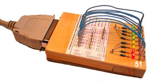
51 General connection board (Generelt tilkoblingsbrett)
The connection
board has 8+4 (12) output lines and 5 input lines which means all standard
inputs and outputs in the old centronics standard. The 8 data-bits which normally
carries codes for different letters is in the figure connected to 8 different
LED's which is there to show the status for different lines. Note that the 17
contacts on the board are connected direct to the printer port in the computer
and on should not connect output lines direct to ground because that could overload
the printer port. Normally this direct connection to the printer port is ok and we have not experienced that the printer port has been damaged.
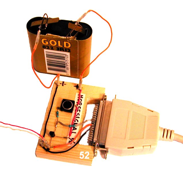 52
Connection board for morse training (Tilkoblingsbrett for morsetrening)
52
Connection board for morse training (Tilkoblingsbrett for morsetrening)
Signaling with morse-signals have shown to be a popular activity and a useful
starting activity before introducing more modern information coding. Therefore a simple connection between morse-equipments that children can
make and a computer is developed. There has also been developed a computer program that can
receive and send morse codes through this board. Inside the computer the information
is transformed to/from normal text on the screen/the keyboard. The batteri is
connected to the board to support power when signal is sent from the computer/the
board. To this board we can connect as many morse-stations we want, but
only one may signal at a time - all other have to listen. The switch on
the board is placed there to make it easy to input test morse signals. Note that
if the computer input line which are used here is "hung high" (is
5V when not in use, normal on most computers), the computer will receive a everlasting
signal and therefore we have to connect for example a LED to the line
output from the board. That will keep the input to the computer low as long
as we not push on the button or the computer it self makes signals.
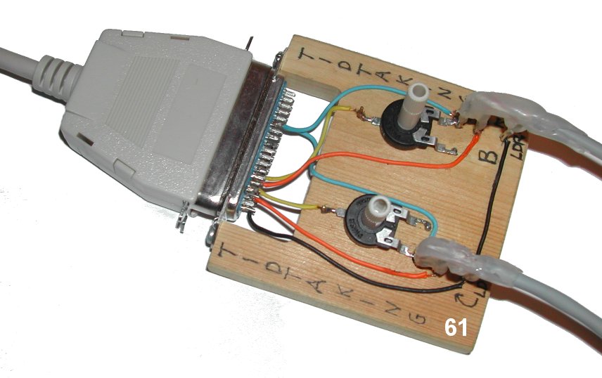 61
Timing board (tidtakingsbrett)
61
Timing board (tidtakingsbrett)
When we want to measure small time intervals
or measure time very accurate, we have to use electronics. If we have a computer,
it is rather easy to us the printer port for time measuring with accuracy around
1 ms. The timing board to the right has two input lines (A and B) and in the
figure there are connected two shielded cables which ends up in some variable
resistors,
for example LDR. The two potensiometers then regulates the level of light
where the input signal shall switches between high and low. The power is supplied
from output-lines from the computer and the program and the build in clock follows standards that
makes it easy to make a program that can measure all sorts of time down
to ms in an easy
way. Because time is one component in velocity and acceleration, this equipment
can also be used to measure these concepts if we make smal changes in
the computer program.
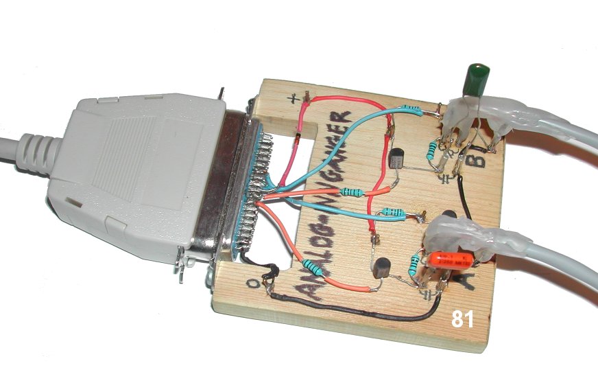 81
Analogous RC-measuring (analog RC-mĺling)
81
Analogous RC-measuring (analog RC-mĺling)
A computer is based on
two values/levels which we often call '0' (no voltage) and '1' (voltage, around
5V in the printer port). In our daily life we are
surrounded by analogous quantities such as light and temperature. Often we
want to measure more than two values for light as we do with the timing board above
(over and under a chosen limit). Much of our modern electronic equipments are
used to measure or sample analogous signals as light, sound and other in
a more accurate way than two levels. The board on the left do just that and
it uses the same principle as modern electronic equipments. In addition to
making quite accurate measurement, it also serves as a simple example which may
help us to understand the basics in modern electronics.
This board have two analogous input (A and B) where we see a shielded cable which for example leads to a LDR (Light Dependent Resistor) and a NTC (Temperature dependent resistor). It also has a power connection where we can connect a 4,5V battery, but it is not always necessary if it is possible to get som power from one of the lines out from the printer port. In addition to the variable resistor in the end of the shielded cable, there is also connected a condenser to each port (red and green in the picture). The mode of operation is then that a computer program opens a transistor so that the condenser is charged. The computer then measure the time from the charging stops till it gets a signal of uncharged condenser through the other transistor. Because the discharging of the condenser goes through the variable resistor, there will be a connection between discharging timen and the light or temperature value and the program may be calibrated to measure for example temperature with a resolution of 0.01°C.
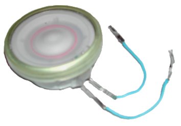 41
Load speaker (hřytaler)
41
Load speaker (hřytaler)
When experimenting with the Electronic
Puzzle, a load speaker
is useful and here we will recommend to pick out some load speakers form ruined
electronic equipment before throwing it away. The picture shows a load speaker
(or a microphone) from a telephone. Note that a load speaker normally also can
be used as a microphone.
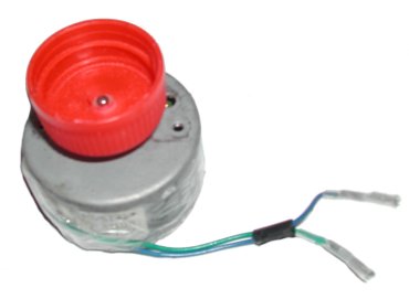 71
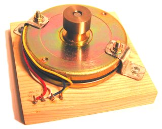
Electro motor for direct current (elektromotor for likestrřm)
71
Electro motor for direct current (elektromotor for likestrřm)
Electronic
equipment as cassette player and other equipment with for example automatic output
for CDs or cassettes have some smal electro motors which should be picked
out before sending away ruined equipment. The picture to the left shows an electro
motor from a video-recorder which function well on voltage around 4,5V. Note
that motors should have just 2 input contacts as shown here and you should only
pick up motors that runs om direct current with low voltage. Other motors may
be difficult to operate or it may only operate on dangerous high voltages. Note also that
those small electro motors may function as generators and they produce direct
current when they are manually turned around. The motor in the picture have
got a bottle top on the axis to hold a homemade fan made of a bottle.
![]() 72
Powertransistor (effekttransistor)
72
Powertransistor (effekttransistor)
Some electro motors can be driven
direct from a printer port, but normally we have to get current from an other
source that can give more power (battery). We then get control signals from
the computer. It is possible to by power transistors for that use. The board
on the right shows a home-made power transistor that can deliver 3 times more
power than one transistor and it can be used to control the power input to an
electro motor.
 73
Step motor (stepmotor)
73
Step motor (stepmotor)
A step motor is a motor that is driven by electrical
current, but it differs from ordinary motors because it may be stopped in many
different angels with exact value. The step motor to the left is from an disk
drive from an older computer and it has been used to position the read/write
head in different tracks on the floppy. This motor normally need a rather advanced
controlling unit, but it is rather easy to control it by using four of the output
lines from a printer port on a computer.
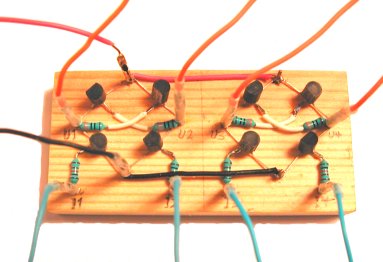 74
Powersupply which may change current direction (kraftforsyning som kan snu
strřmretningen)
74
Powersupply which may change current direction (kraftforsyning som kan snu
strřmretningen)
When we use a computer to control an electro motor or a step-motor
the signals from the computer have low power, and therefore we have to get more
power from another source (a battery). The board on the right gets power through
the red and black lines from the left and gets signals through the four blue
lines. The output is then the four orange lines. If we uses half of the board
we can control an normal electro motor and make it go both directions with different
speeds controlled through a simple computer program through two output lines
from the printer port. If we use the whole board, we can control a step motor
in the same way through a slight more complex computer program.
Here we have shown some general basic boards, but there are no limits for what sort of board the user can make for different usage. The main principle here is that we use some cheap basic components and puts them together in a well arranged way so that it is easy to understand what is going on in the different parts of the puzzle. A normal procedure is then to experiment with the electronic puzzle that is shown above, and if the result is something useful, it is then possible to make some more compact boards which are more useful in practice but usually less easy to understand by just looking at them.
13.2.04 Erling Skaar